Search for answers or browse our help center.
Untitled
Replacement of actuator on Hill Adjustable
INS-20A For tables built before 2/2004
Tools Required: A heat gun or propane torch, a Vise-grip chain wrench or a 24″ (or larger)pipe wrench, permanent thread locker, wire cutters or knife to cut wire ties, 1/4″ allen wrench, 9/16″ box end wrench, small wire brush.
- Turn the able upside down.
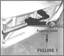
- Heat the ast inch of the actuator adaptor tube where it joins the ball nut to soften the old lock-tite in the threads.
- Using the chain wrench or pipe wrench, unscrew the actuator ball nut from the gray actuator adapter tube (see FIGURE 1). The table may have to be run to a higher or lower position to release one from the other. Use the wire brush to remove hardened lock-tite from tube threads.
NOTE: Right hand threads – standard.
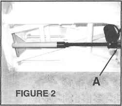
- Unbolt actuator using a 1/4″ allen wrench and the 9/16″ box wrench. (see FIGURE 2)
- UNPLU9 TABLE.
- Cut wire ties and remove:
-White actuator wire from white power cord.
-Black actuator wire from capacitor
-Red a uator wire from Q_ther side of capacitor.
Actuato and motor assembly can now be removed.
- Apply permanent thread locker to the threads of the ball nut on e replacement actuator. Start the threads by hand and then tighten with the chain or pipe wrench. IMPO TANT: Be careful not to crossthread
- Rewire:
-White ower cord to white actuator wire.
-Black actuator wire to red foot pedal wire on one side of capacitpr.
-Red actuator wire to white foot pedal wire.
- Plug table back in.
- Bolt in hew actuator and apply wire ties to the above connections. In order to line up allen bolt with the bolt hole, it may be necessary to tap the foot pedal up or down while holding on to the motor. This will lengthen or shorten the actuator and align the holes.
- Return defective actuator to Hill Laboratories Company.
Avoid running the table to the lowest or highest position for twelve hours in order for the thread lock adhesive to adhere.