Search for answers or browse our help center.
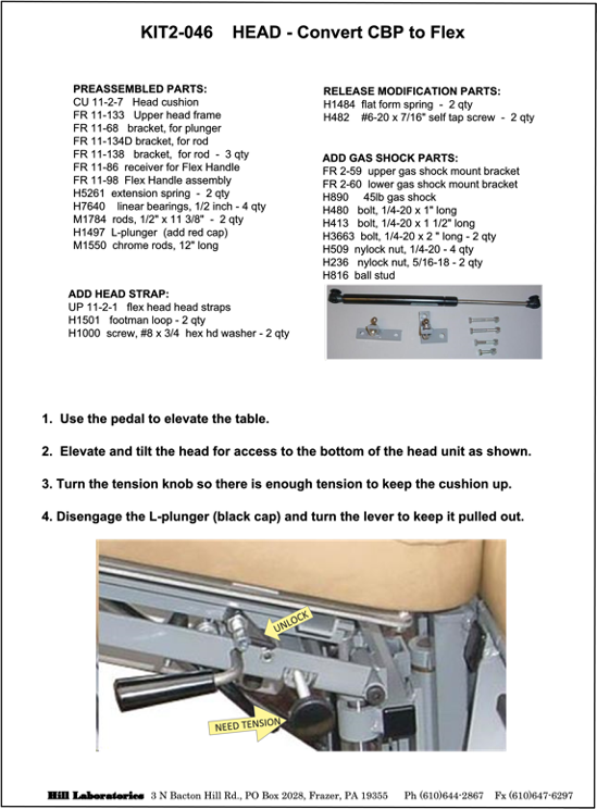
Convert CBP to Flex
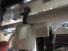
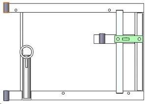
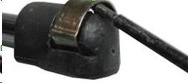
5. Locate the shoulder bolt at the top of the white plastic link. See photo. Use a 3/8″ wrench to remove the nut on the other end of the bolt.
6. Use a 1/8″ hex wrench to remove the shoulder bolt from the white plastic links. The upper frame with cushion will lift off.
7. Orient the lower gas shock mount bracket against the head glide frame as shown. The frame does not need to be removed from the table. Mark and drill 5/16″ through both hole locations. Secure the bracket with the 1″ and 1 1/2″ long bolts and nylock nuts.
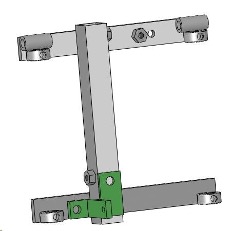
8. Orient the upper gas shock mount bracket against the head glide frame as shown. The frame does not need to be removed from the table. Mark and drill 5/16″ through both hole locations. Secure the bracket with the two 2″ long bolts and nylock nuts.
9. Install the gas shock by pushing each end onto a ball stud. Use a small flat blade screw driver to lift the retainer clip if the gas shock should ever need to be removed.
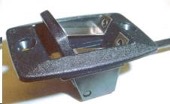
10. Locate the release trigger for the Tilt function so you can add a “locking” feature.
-Push the lever away from the edge of the housing where the cable exits.
-Insert the two platform springs under the release lever as shown in the photo.
-Secure the two springs into the side of the black plastic housing with the two self-tapping screws enclosed.
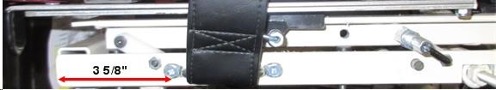
11. To add head strap brackets drill 5/32″ holes at two locations on each side of the lower frame. The first hole can be 3 5/8″ from the end of the frame. Use the strap bracket to mark the second hole. The holes are 1/2″ from the bottom of the frame. Insert the bracket in the strap and secure the brackets with the screws provided.
REVERSE STEPS 1 – 6 TO ATTACH THE NEW UPPER HEAD FRAME.
Note: The pin protruding from the top of the drop pin must be inside the L-shaped hook on the bottom off of the new frame. See photo for orientation. You may need to loosen the tension knob a little so you can rotate the drop pin.