Search for answers or browse our help center.
PLC Power Connector
AirFlex 2 Pow er Connector to the PLC
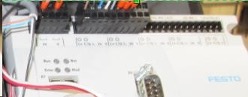
- Location of the PLC.
You can use the Height pedal to low er the table so that you can see these com ponents through the gap in the skirting at the foot end of the table. You can get easier access to the com ponents by removing the screw that holds the plastic to the top frame as you face the foot end and also the screw that holds the inner section to the base at the foot end.
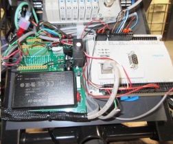
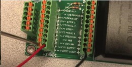
2. Power to the PLC
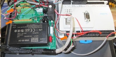
The red and black wires to the first terminals of the small green circuit board supply power indicated by the two orange arrows at left to the connector in the lower left corner of the LC, see third orange arrow at lower center.
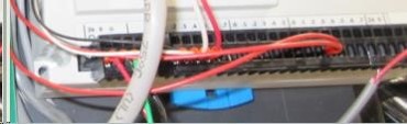
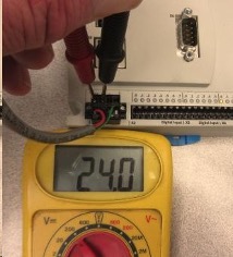
3. Power Connection on the PLC
When power (24volts DC) is received at the PLC the circle below the “24” will be green and several of the LED’s w ill be illuminated along the top of the PLC. A meter can be used to see if 24volts is being received to the connector. Touch one probe to the metal area above the red wire and the other probe on the metal above the black wire. The metal is very visible in the first photo.
4. Verify Connections.
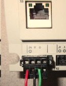
If the touchscreen pow ers up but there is no voltage to the connector at the PLC per Step 3 than you can verify that the w ires are secure at the PLC and also that the sam e red and black w ires are secure at the first term ials of the sm all green circuit board. U nplug the table w hen disconnecting and connecting.
use a very small flat blade screw driver to insert in the metal area of the connector as far away from the wire as you can and then tilt the handle away from the wire to release.
AT CIRCUIT BOARD:
5. Replace the PLC.
If there is power to the PLC yet there are no LED’s then the PLC needs to be replaced.
Make sure the table is unplugged while disconnecting and connecting wires.
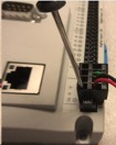
The communication cable is disconnected by hand similar as you would a phone cable by pressing the tab indicated by the pen in the photo with your thumb.