How Can We Help?
Search for answers or browse our help center.
Add Tape Switches to 115V
KIT PREP, TAPE SWITCHES TO 115V
KIT17-002
KIT PREP – Preassemble as shown
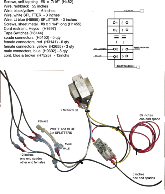
PARTS:
Transform er, 115V (H 5225)
Relay, S ingle Pole ice cube (H 5343) Omron LY 1 24V AC or Tyco K 10P -11A 15-24 Relay socket (H 430)
INSTALLATION INSTRUCTIONS:
- Use the foot pedal to elevate the table.
- Remove the screws securing the inner plastic skirt to the base and lift the skirt.
- Drill a 5/8″ hole in the metal strip at the head end about four inches from where the power cord enters unless one already exists.
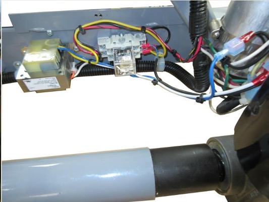
- Mount the transformer and base for the relay to the inside of the base side tube as shown. The transformer is secured w ith the 1/2″ long self-tapping screws. The relay base is secured by pre-drilling 5/32″ holes and securing with the 1 1/4″ sheet metal screws.
5. Insert the 12″ cord with blue and brow n w ires and also the other leads from the tape sw itch w ith red fem ale connectors through the hole in the base (Step3). Connect both spades to #7 terminal of the relay base.
6. BLUE WIRE SPLITTER – The two tape switch wires not connected to the relay will join the blue male connectors of the blue splitter. The yellow female connector of the splitter connects to blue wire from the transformer.
- Locate the main wire harness already in the base. Find the Black/yellow wire in the harness, near the capacitor. Cut it and strip the two ends. Connect the upper end of the cut black/yellow connector to the 6 inch black/yellow from the relay and crimp them together in the yellow connector that is provided. The low er end of the cut black/yellow gets a blue male connector crimped to it. Connect these yellow and blue connectors.
- WHITE WIRE SPLITTER – Locate the white wire from the power cord and separate the connectors. Plug the male connector into a female of the white jumper. Connect the female end of the power white into the blue male of the white jum per. This jumper is connected to the white wire from the transformer.
- The new RED/black wire will follow the original wire harness up the scissor to the control box.
- IN THE CONTROL BOX – Find the red wire to the selector switch and separate the connectors. Plug the new RED/black into the red still connected to the Selector Switch.
- Use electrical tape to “tape off” the original red wire that entered the box.