How Can We Help?
Search for answers or browse our help center.
Kit Prep – Tape Switches to 115V
KIT PREP, TAPE SW ITCHES TO 115V
KIT17-002
KIT PREP – Preassem ble as shown
PARTS:
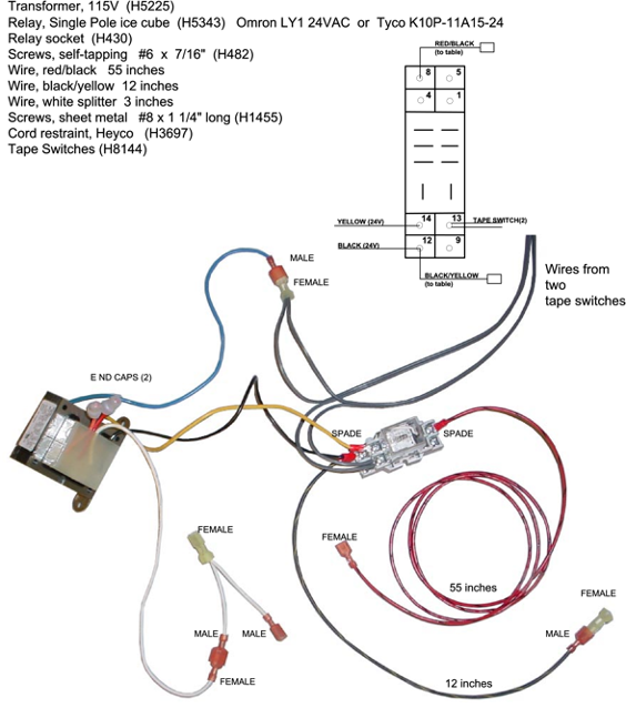
TAPE SWITCHES
-How to Add-
- Use the foot pedal to elevate the table.
- Remove the screw s securing the inner plastic skirt to the base.
- Drill a 5/8″ hole in the metal strip at the head end about four inches from w here the power cord enters.
- Stand at the head end of the table and lift it until the table stands resting on the foot cushion.
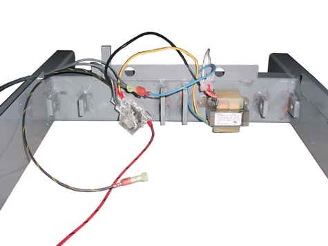
- Mount the transformer on the inside of the base and to the right side of the height actuator. It is secured w ith the self-tapping screws, enclosed.
TAPE SWITCHES
-How to Add-
- Remove the gray wire(s) of the tape switch from the #7 terminal of the relay and insert them through the hole that w as drilled in Step 3.
- The wire from the tape switch with the yellow connector joins with the blue wire from the transformer.
- Connect the gray wires that w ere inserted through the base in Step 6 and connect to terminal 7 of the relay again.
- Locate the main w ire harness already in the base. Find the Black with yellow wire in the harness, near the capacitor. Cut it, strip the two ends, and crimp them together in the yellow connector that is provided. Connect this connector to the BLACK/yellow from the relay.
- Locate the white wire from the power cord. Cut it, strip the two ends, and crimp them together in the other yellow connector provided. Plug this connector into the white wire from the transformer.
- The new RED/black wire will follow the original wire harness up the scissor to the control box.
- Find the red wire to the selector switch and separate the connectors. Plug the new RED/black into the red still connected to the Selector Sw itch. Use electrical tape to “tape off” the original red wire that entered the box.