How Can We Help?
Search for answers or browse our help center.
Add Auto-Return Function
PODIATRY TABLE
Function Add Auto-return
PARTS LIST:
C M 129 A return Board (H 4970) with standoffs
P ush button (H 2500)
“Auto R return” label for the pedal assembly
M micro switch (H 5943) Wire Ties, 6-inch push mount (H 8335) – 8 qty
screws, #6-20 x 1 1/2″ long (H 773) – 2 qty
female connectors – 12 qty
ring connectors (H 5108) – 2 qty
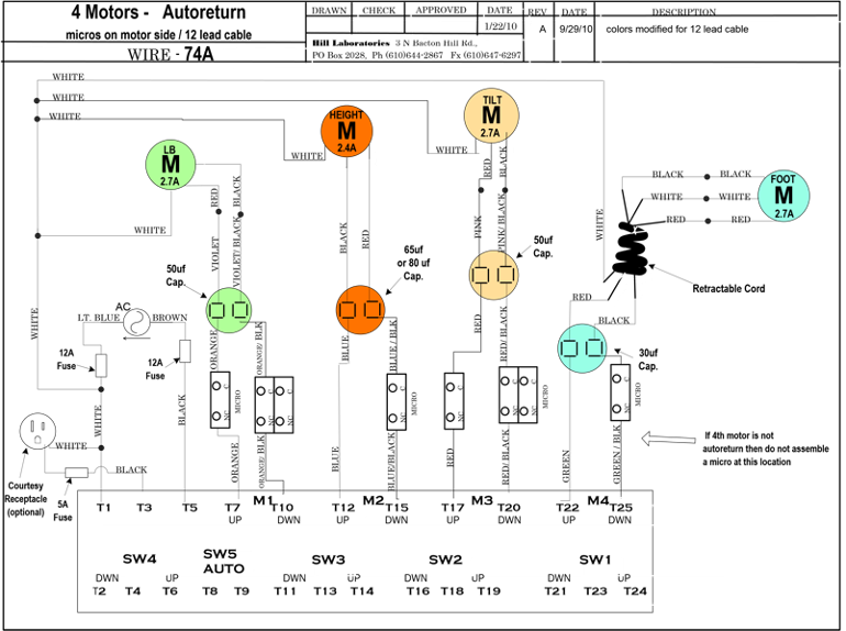
orange wire – 50″ and 60″ lengths w ire diagram
- Unplug the table.
- Disconnect all wires from the original board. There is no need to label wires. The wire sequence will be different on the new board. A wiring diagram is provided.
- Rem the original board and install the new board.
- Refer to the wiring diagram for the new wire color sequence on the board. Note the two wires that were not originally connected. They are wire tied against the inside of the base where the cable enters. Add female connectors to the end of each and connect to SW 5 terminals on the board.
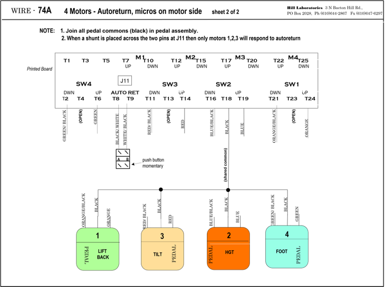
- Remove the black plastic end cap from the right side of the pedal assembly and add female connectors to the two wires hidden inside. Connect the wires to the push
button switch and insert the switch into the end of the steel tube. Adhere the “Auto Return” label to the top of the pedal assembly.