Search for answers or browse our help center.
-
Table Base - General
- Actuator lubrication
- Actuator Mount Plate
- Add 1" of Height to a Stationary Base
- Add 5 1/2 Inches to Height
- Add 9 Inches to Height
- Add 9 Inches to Height of the Base
- Add a Push Button Switch to Cut Off Power
- Add a Tape Switch to Tape Switches
- Add Casters to a Base
- Add Corded Pedal to a Rocker
- Add Double Touch if No Board
- Add Hand Switch to Table
- Add Height to Table with a Rocker Pedal
- Add Height with Level Feet
- Add Length and Width Extensions
- Add Length Extensions
- Add Length Extensions to Level Feet
- Add Level Foot
- Add Spacer at Pivot Points
- Add Two Rocker Hand Switches
- Add Width Extensions
- Adding a Corded Pedal to a Table with One Corded Foot Pedal
- Adding a Rocker to an Extended Height Table
- Adding a Second Pressure Pedal
- Adding Bolt-on Width Extensions to a Base
- Adding Casters to Table with Leveling Feet
- Adding Length Extensions
- Adhere Velcro on Skirt to Prevent Rubbing
- Adjust "Limit Down" Micro Switch
- Auto Return - Replace the Switch
- Auto return board compared
- Auto Touch Foot Pedal Trouble Shooting
- Bolt on Foot Pad
- Caster Assembly
- Circuit board wire color template
- CM129 4-motor board diagram
- CM132 4-motor board diagram
- CM132 and Bostek switch compared
- CM132 PC Board Relay Identification Image
- CONVERT CM132 board to 230V
- Flat Cover Panel, with Luxo holes
- How to Add Tape Switches
- How to lubricate scissor pins
- How to move foot section wires on board
- How to move height section wires on board
- How to move lift back section wires on board
- How to replace a circuit board (for boards CM129 and CM132)
- How to temporarily bypass the circuit board
- How to use the Double-Touch Foot Pedal
- Install "Limit Down" Micro Switch
- Install a Micro Switch (For Tables With a Printed Board)
- Install Micro Switch(s) for tables with printed board
- Install Micro Switches
- Limit / micro switch locations
- Mechlock Release
- Move Hand Switch Receptacle to End of Base with the Board
- My table height will not go down when using the foot pedal
- Replace a Pedal Assembly
- Replace Actuator (After February 2004)
- Replace Actuator (February 2004 - Present)
- Replace Actuator and Actuator Adapter
- Replace B-1 Bushings
- Replace Brake Assembly or Worm Gear, noise in elevation motor
- Replace Capacitor
- Replace Circuit Board CM132 with CM129 for tables built between May 2011 to present
- Replace Circuit Board CM132 with CM129 for tables built between Oct 2010 and May 2011
- Replace Corded Pedal
- Replace Corded Wire
- Replace Corded Wire 2 (No Board)
- Replace Corded Wire 45 W/ Board
- Replace Corded Wire 79A
- Replace Power Cord
- Replace Switch in Hand Rocker
- Replace the AutoTouch Board
- Replace the Circuit Board
- Replacing a Corded Pedal
- Replacing a Rocker at Head End with a Corded Pedal
- Replacing a Rocker at Middle of base with a Corded Pedal
- Replacing a rocker foot pedal with corded
- Replacing the B-1 Bushings
- Replacing the Height Actuator in a Base For bases built after February 2004
- Replacing the Lower Scissor Pins
- Replacing the Motor Only
- Replacing the rocker foot pedal switch
- Replacing the Scissor Pins
- RFI Filter
- Rocker Foot Pedal - Align
- Rocker foot pedal alignment
- Shorten the Base
- Squeal noise at the top of height
- Switches Inside
- Threaded Insert, Level Feet
- Troubleshooting auto touch
- Troubleshooting swivel lock
- Wire 2 One Motor, Single Pedal
- Wire diagram for board & pedal assembly for 2, 3 4 motor tables
- Show all articles (81) Collapse Articles
Add Double Touch if No Board

Preassemble:
- mount plate #1085B – 1
- micro switch – 2
- WIRES – Black- 20″(2)
White- 3″(2), 20″(2), 24″, and 40″
Red- 15″, 20″, and 29″
- CONNECTORS –
Female – Red – 11 Blue – 1
Male – Red – 5
Terminal Ring – 4
- stand-offs – 4 6. zip loom – 35″
Also send:
7. flat head screws to mount micro – 4 8. screw s – #8 x 3/4 long hex hd sheet metal
PREP WIRES :
15″ Red – F and Ring
29″ Red – F and Ring “N C ” on micro
24″ White – F and Ring “C ” on micro
40″ White – F and Ring “N C ” on micro
3″ White(jum per) – crimped with another
20″ White – F and F “115A C ” on board
20″ Black – F and F “115A C ” on board
20″ Red – F and M “S W
20″ White – F and M “S W 20” B lack – F and M “S W
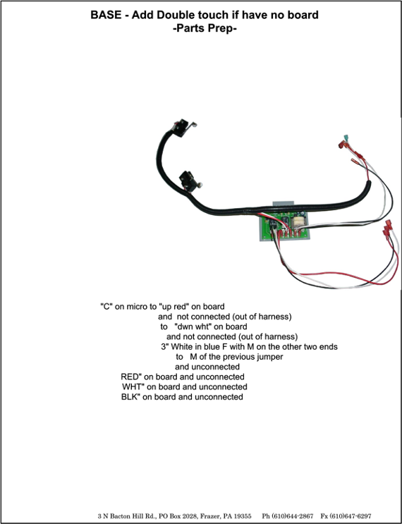
HARNESS:
white micro exits one end red micro exits at about 10″ of harness shorter red & white wires exit at about 19″ to connect to board longer red and white continue out the other end
BOARD:
mount board to plate with standoffs