Search for answers or browse our help center.
-
Air Flex
-
- Adjusting old style rotation (1993 - 2003)
- Air manifold diagram (2012-2018)
- Alignment of lumbar drop pin on a thoracic & lumbar drop frame
- Auto distraction Kelly connections (2010-2018)
- Auto distraction patient stop switch override (2010-2018)
- Auto distraction patient switch enable
- Auto distraction safety relief valve connected to distraction cylinder (2006-2009)
- Auto flex motor connector (2011-2018)
- Check valve location (2007-2011)
- Hose identification on manifold (2012-2018)
- How to Add Gas Shock to Dual Drop with Raise Feature
- How to add tapeswitches to table (pre-2012)
- How to adjust air pressure on pressure switch (1997-2011)
- How to adjust elevator bolt for auto flex (1999-2018)
- How to adjust lateral lock lever
- How to adjust length of drop on air cylinders
- How to adjust rotation lock handle (2004-present)
- How to adjust the stroke on a thoracic breakaway cylinder
- How to align centering pin and cam on pelvic rotation (2004-present)
- How to attach mechlok mount bracket for tilt head
- How to attach repair bracket for mechlok mount on thoracic frame
- How to attach the pancake cylinder bracket
- How to change out large green board (2012-2018)
- How to check auto distraction connections (2010-2018)
- How to check foot pedal connections (2012-2018)
- How to check squeaking on flexion
- How to disable cervical distraction function (2010-2018)
- How to enable options on touchscreen (2010-2018)
- How to Identify a Kelly Valve Revision / Version for Replacement
- How to lock out rotation on pelvic section (1993-2001)
- How to lock pelvic rotation (2004-present)
- How to lubricate the lateral motion
- How to mute sound on touchscreen (2010-2018)
- How to prevent pull out ankle from jamming when pushed in
- How to purge a valve (2012-2018)
- How to remove auto distraction feature with auto flex (2010-2011)
- How to remove wobble from flex lock handle (1993-2018)
- How to replace a valve on the manifold (2012-2018)
- How to reset the click (PLC) for auto distraction or auto flexion (2010-2018)
- How to tighten pelvic rotation (1993-3/2006)
- How to tighten set screw on parker auto flex motor
- How to tighten the auto flex gear on the motor shaft (12/2006-2018)
- How to troubleshoot air coming out of unloader (1993-2011)
- How to troubleshoot weak drops (2012-2018)
- If the distraction doesn't glide smooth
- INS-04 Replacing Rotation Lock Assembly (1999-2003)
- INS-104B Adjusting the Rotation Lock (pre-2003)
- INS-123 Instructions for Converting Regular Height to Short Height
- INS-126 How to replace the check valve (1993-2011)
- INS-5A Instructions for replacing a coil on the valve bank (1993-2011)
- INS-77 Instructions for changing the short cable assembly
- Inspecting height capacitor wires
- Installing a Lock-Out device for the Pelvic Rotation (2001-2003)
- Installing firmware (2012-2018)
- Locating a broken bolt on the lifter tube assembly
- Marshbellofram connections for Auto Distraction (2006-2009)
- Marshbellowfram air line connections (2006-2009
- Pelvic drop does not stay up
- Quick set guide for auto distraction
- Rebuilding Allenair Air Cylinders (1993-6/2007)
- Reed switch test (3/2004-12/2006)
- Replacing the Linear Bearing in a Drop Mechanism
- Repositioning rotation pin with no pelvic drop (2004-present)
- Repositioning rotation pin with pelvic drop (2004-present)
- Rotation lock engaging reference (2004-present)
- Temporary by-pass of auto distraction (2006-2011)
- Tightening the Lateral Lock Adjustment
- Troubleshooting auto distraction with a marshbellowfram
- Troubleshooting auto flex motor not starting (2011-2018)
- Troubleshooting coil and valve (1993-2011)
- Troubleshooting green board or power button shutting down (2012-2018)
- Troubleshooting thoracic & lumbar drops
- Valve manifold identification (2012-2018)
- Verifying the pelvic rotation centering pin (2004-present)
- What to check if compressor never shuts off
- Show all articles (60) Collapse Articles
-
- Add tape switch (tables beginning Jan 2019)
- Add Tape Switch (Tables January 2019 - Present)
- Air Flex II Power Switch
- Change HMI
- Changing HMI on an Air Flex II Table (2010 - 2018)
- Communication Cable Connection
- How to change or replace the touchscreen (HMI)
- How to Replace the Check Valve
- How to Replace the Communication Cable Connection
- PLC Power Connector
- Power Connector to the PLC
- Replace PLC
- Replace the Harness for a Touch Screen
- Replace the Power Supply Board
- Replace the VPPM
- Replace Unloader Valve, Air Flex II, Tables 2019 - Current
- Replacing the PLC
- Replacing the Power Supply Board
- Replacing the unloader valve
- What version is my firmware?
- Show all articles (5) Collapse Articles
- 3-Way Switch Wiring Diagram
- 4-Drop air hose layout (1993-2011)
- 4-Way Switch Diagram
- Add a Filter
- Add a Tape Switch to Tape Switches
- Add Auto-Drain Air Filter
- Add AutoFlex Feature
- Add Distraction - Only Add Lumbar
- Add Double Touch to a Table w/ No Printed Board
- Add Drop Function to an 8-inch Cushion
- Add Drop Function to an 8in Cushion
- Add Filter to Airflex
- Add Flex Head Head or CBP Head
- Add Flex Head or CBP Head
- Add Flow Control to the Pelvic Drop
- Add Rotation
- Add Second Bolt-On Control Box
- Add Second Control Box
- Add Side Supports
- Add Square Tape Switch Above Touch Screen
- Add Tape Switch ( Airflex 2012 - 2018; AirC/Deluxe AFT 2012 - Present)
- Add Thoracic Breakaway
- Adding a Corded Pedal to a Table with One Corded Foot Pedal
- Adding a Gripper Bar Assembly
- Adding Flow Control Valves (Valve Restrictors) to Air Drops
- Adjustable Rotation Lockout Bar
- Adjusting the Flex Position Sensor (January 2019 - Present)
- Air Flex Auto Distraction (Tables Built Feb 2010 - Dec 2018)
- Airflex Ankle Mechlok
- Ankle Mechlok Stop
- Bolt-on Gripper Bars Set
- Cervical Tilt Mechlok Unit
- Change height from 22.5" to 21.5"
- Compressor Capacitor
- Control box location mounted on cushion (1993-2011)
- Cushion Post Assembly
- Cylinder Rebuild
- Finger Guards
- Flex Lock Rack Replacement
- Flow Control Valve
- Flow Control Valve for 8 in Thoracic and Lumbar Drops
- How to Add Flow Control to the Pelvic Drop of an Air Flex Table
- How to Disconnect the Air Cylinder on an Air Flex Table
- How to Mount a Pelvic Cushion onto an Air Flex Table
- How to Replace a Tape Switch on an Air Flex Table
- How to Replace the Upper Pivot Lock Lever on an Air Flex Table
- If scissor pin loosens or comes out
- Increase Hose Size from the Compressor
- Install Sleeve Bushing
- Install Snap-Grip
- Installing raised Ankle on AFT or Airflow
- Lumbar Cylinder Mount
- Manifold Valve
- Modify Original Cushions for New Style Drop Rods
- Modify Thoracic Cushion
- Modifying "Long" (18 3/4") Pelvic Cushion for Rotation with Mechlok
- Motor Terminal Block
- Mount at Square End of Thoracic Cushion
- Mount for Lateral Head Mechlok
- Mounting a Mechlok Release
- New Motor Wiring
- Pancake Repair
- Pelvic Cushion Spacer
- Pelvic Drop Rod Washer
- Pelvic Drop, Steel Ball
- Power Supply (After 2003)
- Pressure Gauge Replace
- Rebuild Compressor
- Reed switch mounting (2011-2018)
- Relocate Mechlok Mount Tube Relative to the Hinges
- Remove the Selector Knob from Socket
- Removing Cushions
- Repair Bracket for Mechlok Mount on Thoracic Subframe
- Repair Bracket for Mounting the Thoracic Mechlok (Tables January 2013 - Present)
- Repair Bracket for Mounting Thoracic Mechlok
- Repair Coupling Nut
- Repairing the Head Piece Mechlok Unit
- Replace 6-Gang Manifold
- Replace a Tape Switch
- Replace a Valve on the Manifold
- Replace Air Compressor
- Replace Air Filter
- Replace Air Filter (April 2007 - Present)
- Replace Air Filter (Tables before April 2007)
- Replace Allenair Felxion Cylinder with Festo Brand
- Replace Board in Control Box
- Replace Check Valve
- Replace Distraction Assembly
- Replace Distraction Frame Only
- Replace Flat Spring
- Replace Flex Lock and Flexion Cylinder
- Replace Flex Lock Assembly
- Replace Flexion Cylinder
- Replace Flexlock Assembly
- Replace Furnace Brand Pressure Switch (Tables Built Before March 1997)
- Replace Furnace Brand Pressure Switch (Tables Made March 1997 - Present)
- Replace Gast Air Compressor
- Replace Marsh Bello Fram with Kelly and Touchscreen
- Replace Mechlok Mount (Airflex 2013 - Current)
- Replace Mechlok Mount (Tables 2013 - Current)
- Replace Original Distraction Cylinder with 2-inch
- Replace Pelvic Drop Pin
- Replace Pressure Pedal
- Replace Pressure Switch, but Keep Original 2-Ware Compressor
- Replace Raised Head with Lateral Raised Flex Head or CBP
- Replace Reed Switches (February 2008 - June 2009)
- Replace Reed Switches (Tables thru Feb 2008)
- Replace Rotation Lock Cam
- Replace Spring in Thoracic or Lumbar
- Replace Square-D Pressure Switch
- Replace Tension Spring in Thoracic & Lumbar
- Replace Tension Spring in Thoracic and Lumbar
- Replace the 4-Position Selector Switch
- Replace the Air Compressor
- Replace the Air Cylinder
- Replace the Air Cylinder Clevis
- Replace the Autoflex Motor
- Replace the Banjo Fitting
- Replace the Click Controller
- Replace the Communication Cable
- Replace the Extension Spring
- Replace the Flex Cylinder (Tables 2019-present)
- Replace the Flex Cylinder (Tables Oct 2007 - Dec 2018)
- Replace the Flex Lock Lever
- Replace the Flex Lock Spring
- Replace the Flex Position Sensor (Tables 2019 - Present)
- Replace the Glide Bar Guide
- Replace the Main Board
- Replace the Plunger Bracket
- Replace the Pressure Relief Valve
- Replace the Solenoid
- Replace Thoracic Breakaway Cylinder
- Replace Thoracic Mechlok
- Replacing a Coil on Deluxe Version
- Replacing a Push Button Switch
- Replacing a Valve
- Replacing a Valve on a Table with 1 or 2 Drops
- Replacing a Valve on Deluxe Version
- Replacing a Wire to the Valve
- Replacing Air Compressor with No Capacitor and 2 Wires With a Compressor That Has a Capacitor and 3 Wires
- Replacing Raised Ankle on AFT or Airflex
- Replacing the Motor on an Autoflex
- Replacing the Plastic Air Tank
- Rotation lock out explanation (1993-2003)
- Rotation Pivet Weldment (Yoke) Replacement
- Rotation Pivot Casting Replace
- SMC to Festo Replace
- Spartan air hose diagram (1993)
- Tension Knob Friction Plates
- Thoracic and lumbar drop pin assembly
- Thoracic Breakaway - Flow Control Valve
- Thoracic Cable Routing
- Thoracic drop pin alignment
- Thoracic mechlock release with air cylinder
- Turn off Sound to Touch Screen
- Unloader Valve
- Untitled
- When Gear on Motor is Not Staying Engaged
- Wire Colors for Board Replace
- Wire Harness
- Wiring of control box for deluxe (Rear View)(1993-2011)
- Show all articles (146) Collapse Articles
-
Replace Marsh Bello Fram with Kelly and Touchscreen
AUTO DISTRACTION
Replace Marsh Bello Fram with Kelly and Touchscreen
- U se the pedal to elevate the table to its highest elevation.
- UNPLUG the table.
- Remove the inner and outer sections of skirt.
- Detach hoses from the original air regulator (Marsh Bello Fram ) only. See photo for the regulator location.
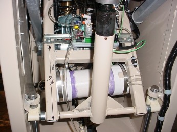
5. Leave the ground wire attached to frame. Detach all wires from the original Marsh Bello Fram air regulator.
6. Remove the original Marsh Bello Fram regulator from the din rail by pressing the tabs on the underside of its base, as shown.
7. Remove the control box from the cushion and the telephone wire that is routed through the table. IMPORTANT: Take note of the route because you will need
to install another cord along the same path in Step 10.
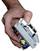
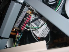
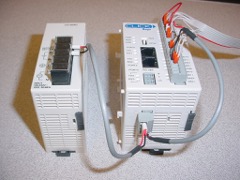
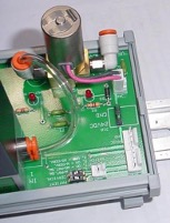
8. Snap the new air regulator (Kelly brand) onto the din rail. The kit also includes a new controller (C lick brand) which MUST BE oriented as in the photo in order to prevent damage when the table height is adjusted.
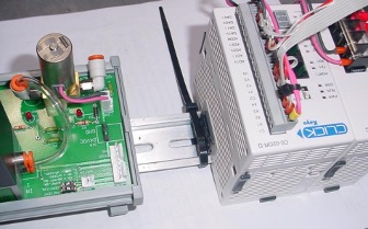
If the table already has a large m etal pow er supply m ounted to the scissor for pow ering the A utoFlex feature then it can also pow er the A utoD istraction feature. The C lick controller can be separated from its pow er supply by sliding the gray clips up to release. C onnect the red w ire to term inal “V +” on the m etal pow er supply and black to “V -“
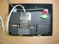
9. Attach the touchscreen hinges to the underside of the cushion at the same location as the control box that you removed.

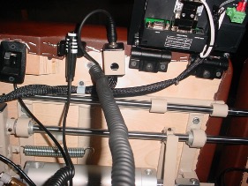
10. Route the wires that are enclosed in the black braided nylon along the same route that the telephone cord had followed. Refer to the three photos for reference where each is connected.
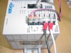
11. Attach the two air hoses by inserting them in the fittings on each side of the regulator.
“1 IN” is printed on the side for the air coming into the regulator and “2 CYL” on the side for the hose going out to the cylinder.
12. Secure the wires to the table with the white cable clamps in the same locations as was used for securing the telephone cable. Refer to the photo below for referencing those near the Patient STOP Switch and Touchscreen.
13. Attach the clamp to hold the Patient STOP Switch, the switch jack, and two hinges for the Touchscreen near the edge of the pelvic cushion, as shown below.